


Abstract
We systematically explore the origin and evolution of the exceptional points (EP) when a light beam is scattered by a parity-time (PT)-symmetric system using a scattering matrix approach and a full-wave theory. It is demonstrated that the PT-symmetric system switches between symmetry and symmetry-breaking phases at the EPs, giving rise to singular features in the Fresnel coefficients and causing the spin-Hall effect (SHE) near the EPs to exhibit anomalous features such as significantly enhanced transverse spin-Hall shifts and additional in-plane spin-Hall shifts. This exotic SHE can be explained by the significant beam intensity distortion caused by the destructive interference between the spin-maintained normal modes and the spin-reversed abnormal modes in the scattered light. This phenomenon can further be understood in terms of vortex mode decomposition, wherein it can be interpreted as the competition and superposition of three vortex modes with topological charges of −1, 0, and 1, respectively. These findings elucidate the mechanism of the unusual SHE around the EPs and offer potential avenues for EP-based sensing and structured light manipulation.

Original content from this work may be used under the terms of the Creative Commons Attribution 4.0 license. Any further distribution of this work must maintain attribution to the author(s) and the title of the work, journal citation and DOI.
1. Introduction
Propagation, scattering, and focusing are fundamental optical processes in which the coupling and conversion between spin and orbital angular momentum can occur, namely the spin-orbit interaction of light [1–5]. Typically, when a light beam is reflected or refracted at optical interfaces, its left-handed circularly polarized (LCP) and right-handed circularly polarized (RCP) components exhibit a transverse spin-dependent shift, known as the spin-Hall effect (SHE) of light [6–14]. Particularly, when linearly polarized beams strike an optical interface at specific angles (e.g. Brewster angle), the SHE of the reflected beam is highly unique, whose intensity pattern is significantly deformed, leading to a pronounced enhancement of the spin-Hall shift [15–19]. Therefore, many efforts have been made to study the unique properties of this anomalous SHE and to explore their potential applications in precision measurement and sensing [20–23].
Non-Hermitian optical systems, where the energy eigenvalues are usually complex and that most of their realizations depend on losses and gains, have attracted widespread interest due to their unique properties [24–26], thus introducing additional degrees of freedom for the manipulation of SHE. Parity-time (PT) symmetric systems are typical examples of the non-Hermitian systems, composed of balanced loss and gain, with the refractive index of the loss and gain materials satisfying the condition of spatial inversion symmetry [27–30]. By adjusting system parameters, such as changing the ratio of loss and gain, spontaneous PT-symmetry breaking can occur, resulting in significant changes in the overall system properties [31–33]. The phase transition points between the symmetric and symmetry-breaking phases of the non–Hermitian system are exceptional points (EPs) where the two eigenvalues and the corresponding eigenstates coalesce to the same value, giving rise to behavior similar to the Brewster effect but with more exotic phenomena, and providing a possible way to manipulate the SHE [34]. Conversely, since the SHE near the EP is extremely sensitive to the system parameters, the position of the EP could be precisely determined by measuring the photonic SHE. However, the underlying mechanisms of the unusual SHE exhibited by EPs have not been well elucidated, thereby limiting further manipulation and application of the SHE.

In this paper, we systematically investigate the generation and evolution of EPs in the scattering of a light beam at a PT-symmetric system through a scattering matrix method, and analyze the SHE of light near the EPs based on a full-wave theory. At the EPs, the system transitions from PT-symmetric phase to symmetry-breaking phases and vice versa, giving rise to singular features in the Fresnel coefficients, such as Brewster-like behavior in s-polarized waves. This introduces an additional phase to the reflected light, resulting in two-lobe rotation intensity and anomalously enhanced transverse spin-Hall shifts, and produces additional in-plane shifts. By examining the Fresnel coefficients corresponding to the spin-maintained normal mode and the spin-reversed abnormal mode, we show that under linearly polarized beam incidence, the LCP or RCP component in the reflected beam must be a combination of the normal and abnormal modes of the reflected beam corresponding to the LCP and RCP components in the incident beam, respectively. The destructive interference effect between these two modes leads to severe distortion of the beam patterns, significantly enhancing the transverse spin-Hall shifts and generating in-plane shifts. Finally, the unusual SHE near the EPs can be understood in terms of vortex mode decomposition, namely, the coupling and competition among three vortex modes with topological charges of 1, ‒1, and 0, respectively.
2. Theory and model
2.1. Full-wave theory of beam scattering in non-Hermitian systems
In general, a PT-symmetric system is composed of gain and loss layers of equal thickness d whose refractive indices satisfy (figure 1). Considering a light beam incident on the PT-symmetric system placed in air, we define (x, y, z) and (xa, ya, za) as the laboratory and local coordinate systems, respectively. Here, the superscripts a = {i,r} denotes the incidence and reflection, respectively. Based on the angular spectrum theory, the electric field of the light beam can be written as [35],


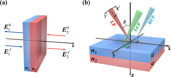
Figure 1. Schematic picture of the SHE of light in the PT-symmetric system. (a) Scattering diagram of a dual-layer PT-symmetric system of a light beam. The input field (, ) is scattered into two output fields (, ). (b) Schematic diagram of the spin-Hall shift of the linearly polarized beam reflected in the non-Hermitian optical system. Here , we set as the loss layer and as the gain layer; d is the thickness of the material, and Δy is the transverse shift of the reflected beam.


Download figure:
Standard image High-resolution imagewhere with , and are the wave vector and position vector in local coordinate system, respectively. denotes unit vectors of LCP (+) and RCP (−), and represents the transverse field of the beam in k-space.


We establish a transfer matrix to connect the incident beam to the reflected beam, namely [35],

Here,

represent the Fresnel reflection coefficient of the circular polarization basis with tangential wave vector k|| defined in the laboratory coordinate system. is a momentum-dependent Pancharatnam–Berry phase [35–39]. is the incident angle of the light beam, and is the azimuthal angle of the incident plane of an any noncentral plane wave, while and are the transverse wave vector components of an arbitrary plane wave in laboratory coordinates. Here, and are the reflection coefficients of the p- and s-polarized plane waves within the beam, respectively. Performing a Fourier transform on the incident field to obtain its angular spectrum , we substitute into equation (2) to get , then the real fields obtained by putting into equation (1) as,


The above two equations represent the spin-maintained normal mode and spin-reversed abnormal mode, respectively. Finally, with a complete understanding of the electric field distribution of the reflected beam, we can use the following formula to calculate the spin-Hall shift of the beam:

where .

2.2. Scattering matrix of PT-symmetric systems
The scattering of a beam in the PT-symmetric optical system can be described by the scattering matrix S, which relates the output electric field (, ) to the input one (, ) (figure 1(a)). Two different scattering matrices with distinct sets of eigenvalues can be defined by the permutation of the outgoing waves, leading to apparent symmetry breaking. These two matrices are and , where and , is the Pauli matrix [40–43]. Here, f (b) denotes the propagation of the beam in the forward (backward) direction along the z-axis, t represents the transmission coefficient (note that ), and signifies the reflection coefficient. The Fresnel coefficients can be calculated with the transfer-matrix method [44]. Although both definitions of the scattering matrix are widely used, it is obvious that the two definitions of Sr and St have different eigenvalues. We provide a detailed analysis of the EPs generated by the scattering matrix St in this paper. The eigenvalues of St are denoted as . According to the generalized conservation relation [31, 45], we have , where represents the transmittance. When , , the system is in the exact PT-symmetric phase. When , , the system exhibits a symmetry-breaking phase. Especially, if , or , the two eigenvalues coalesce into the same value, denoted as an EP.


![${S_t} = \left[ {\begin{array}{*{20}{c}} t&{{r^f}} \\ {{r^b}}&t \end{array}} \right]$](https://content.cld.iop.org/journals/1367-2630/26/10/103010/revision2/njpad825bieqn33.gif)
![${S_r} = \left[ {\begin{array}{*{20}{c}} {{r^f}}&t \\ t&{{r^b}} \end{array}} \right]$](https://content.cld.iop.org/journals/1367-2630/26/10/103010/revision2/njpad825bieqn34.gif)
![$\left[ {\begin{array}{*{20}{c}} {E_1^b} \\ {E_2^f} \end{array}} \right] = {S_t}\left[ {\begin{array}{*{20}{c}} {E_2^b} \\ {E_1^f} \end{array}} \right] \equiv \left[ {\begin{array}{*{20}{c}} t&{{r^f}} \\ {{r^b}}&t \end{array}} \right]\left[ {\begin{array}{*{20}{c}} {E_2^b} \\ {E_1^f} \end{array}} \right]$](https://content.cld.iop.org/journals/1367-2630/26/10/103010/revision2/njpad825bieqn35.gif)

![${\sigma _x} = \left[ {\begin{array}{*{20}{c}} 0&1 \\ 1&0 \end{array}} \right]$](https://content.cld.iop.org/journals/1367-2630/26/10/103010/revision2/njpad825bieqn37.gif)


3. Results and discussion
3.1. EPs of PT-symmetric systems
We utilize the eigenvalues of the scattering matrix St to investigate the formation conditions and evolution of EPs in PT-symmetric systems. Initially, we select several representative refractive indices that adequately demonstrate the various scenarios in which EPs may occur. To illustrate the variation of EPs with changes in system parameters, the evolution curves of the eigenvalues corresponding to p-polarized (the first column) and s-polarized (the second column) waves against the incident angle are plotted separately (figure 2). For the system with a real part of the refractive index nR = 1.5 and an imaginary part of the refractive index nI = 0.5040, the system undergoes a transition from a PT-symmetric phase to a symmetry-breaking phase for both p-polarized and s-polarized incident beams. It returns to the PT-symmetric phase as the incident angle is further increased. In this process, two eigenvalues are merged for both polarizations, corresponding to the two EPs generated (figures 2(a) and (b)). Changing the refractive index to nR= 3 and nI = 0.5040, the p-polarized wave still follows a similar symmetry-breaking pattern as in figure 2(a) and forms two EPs again (figure 2(c)). However, for the s-polarized wave, even under the same refractive index conditions, it maintains a strictly symmetric phase, indicating that no EPs appear for this specific refractive index configuration (figure 2(d)). Nevertheless, under the refractive index setting of nR= 3 and nI = 0.7508, the system directly transitions from a symmetry-breaking phase to a strictly symmetric phase (figures 2(e) and (f)). During this process, only one EP appears for each of the p-polarized and s-polarized wave, demonstrating that small variations in the refractive index can lead to significant changes in the distribution and number of EPs. Furthermore, other system parameters, such as the thickness d, also have a significant impact on the symmetry of the PT-symmetric system.

Figure 2. Modulus of the eigenvalues (|ψ|) of the St for p-polarized wave (first column) and s-polarized wave (second column) in different PT-symmetric systems, where the refractive indices of the bilayer materials satisfy . (a)–(b) real part of the refractive index nR= 1.5 and imaginary part nI = 0.5040; (c)–(d) nR= 3 and nI = 0.5040; (e)–(f) nR= 3 and nI = 0.7508. Here, the thickness of each layer is d = 0.2λ, where λ is the working wavelength.

Download figure:
Standard image High-resolution imageIt is clear from the above discussions that the properties of EPs depend on the refractive index of the materials that make up the PT system, which directly influences the reflection coefficients. To better understand this relationship, figure 3 displays |rp| (the first column) and |rs| (the second column) for the specific refractive index values used in figure 2. As depicted by the EPs in figure 2, at these specific incident angles, the corresponding |rp| and |rs| values are both zero, marking the exact location of the EPs. Moreover, by analyzing the Fresnel coefficients, we can not only confirm the existence of EPs, but also determine the incident direction of the beam. Particularly in PT-symmetric systems, due to the symmetry characteristics of the loss layer and the gain layer, beams exhibit distinct phenomena when entering from each side. Therefore, the accurate determination of the incident direction corresponding to the EPs is crucial. Specifically, in figures 3(a) and (b), where , it indicates that the exotic phenomena associated with EPs can only be observed as the beam is incident from the forward direction of the material (from the loss layer). Conversely, in the scenario depicted in figure 3(c), where , it suggests that the beam must enter the material from the backward direction (i.e. from the gain layer). Also, both |rp| and |rs| in figure 3(d) have no zeros which implies that there is no EP, whereas figures 3(e) and (f) have one zero for |rp| and |rs| respectively, which correlates with the EPs in figures 2(e) and (f). This series of analyses offers an alternative perspective for effectively identifying and exploring EPs in non-Hermitian optical systems.


Figure 3. Reflection coefficients versus incident angles in PT-symmetric systems with the first column for |rp| and the second column for |rs|. The refractive indices are (a)–(b) nR= 1.5 and nI = 0.5040; (c)–(d) nR= 3 and nI = 0.5040; (e)–(f) nR= 3 and nI = 0.7508.
Download figure:
Standard image High-resolution image3.2. Linearly polarized beam scattering at PT-symmetric systems
After knowing the generation regularity of EPs in PT-symmetric systems, we can quickly find the distribution of EPs at different refractive index conditions. To further explore the SHE near the EPs, we now investigate the optical properties near the EPs through a series of full-wave calculations.
Assuming that the incident beam is a p-polarized Gaussian beam composed of the LCP and RCP components of equal intensity, we have , where w0 is half-width of the beam waist. Then, substituting these initial conditions into equations (1) and (2), we get the LCP and RCP components in the reflected beam [13]:
![$U_ + ^i({{\boldsymbol{k}}^i}) = U_ - ^i({{\boldsymbol{k}}^i}) = \exp \left[ { - {{(k_ \bot ^i{w_0})}^2}/4} \right]$](https://content.cld.iop.org/journals/1367-2630/26/10/103010/revision2/njpad825bieqn53.gif)

Equation (6) indicates that and consist of a spin-maintained normal mode and a spin-reversed abnormal mode, whose shifts can be obtained by putting the equation (6) into the equation (5).


By changing the parameters of the PT-symmetric system, a variety of intensity patterns can be obtained. Variations in the refractive index of the system may result in complex patterns exhibiting the rotation of the reflected beam at the EP, as shown in figure 4. Furthermore, by altering the polarization state of the incident beam, such as setting it to elliptical polarization, it is possible to adjust the weights of the normal and abnormal modes (as in equation (6)), thereby controlling the light-intensity distribution and the SHE. In fact, we can also alter the parameters of the PT-symmetric system so that the position of the EP appears at any incident angle, thereby controlling the SHE of light. Conversely, since the intensity distribution of the reflected beam in the PT-symmetric system varies with the refractive indices (nR and nI), we can locate the EP through the SHE.

Figure 4. The intensity distribution at EPs for different imaginary parts of the refractive index in the PT-symmetric system. Here, the real part of the refractive index is fixed as nR = 3 and d = 0.2λ.
Download figure:
Standard image High-resolution imageWe select several particular distributions of light patterns to analyze in detail, which exhibit exotic SHE different from the Brewster effects. Firstly, we analyze the behaviors of p-polarized light incident from the forward direction in the PT-symmetric system. Figure 4(a) illustrates the variations of and (the field intensity of the LCP and RCP components of the reflected beam) with the angle of incidence θi. The intensity distribution patterns of these two components undergo significant changes as varying the θi and have opposite intensity evolutions, forming a two-lobe intensity distribution at EP. It is noteworthy that the phase distributions of the LCP and RCP component have opposite signs at the EP [inset of figure 4(a)], indicating that their intensity distributions have opposite variation characteristics. When the linearly polarized beam is incident on both sides of the EP, the intensity distribution has a noticeable centroid shift in the transverse y-direction, exhibiting a giant and opposite spin-Hall shift (figure 4(b)), i.e. Δy− = −Δy+, In particular, this displacement vanishes at EPs, indicating the complete suppression of the SHE. Besides, there are also in-plane shifts, which reach their maximum value at the EP [inset of figure 5(b)]. Although this value is relatively small compared to the displacement in the y-direction, it is important to note that the SHE is generally a weak phenomenon [7, 8].


Figure 5. Intensity distribution and spin-Hall shifts of the reflected beam near the EP under illumination of a p-polarized beam from the forward direction in the PT-symmetric system. (a) Intensity and phase distributions (insets) of the LCP and RCP components of the reflected beam. (b) Spin-Hall shift. Here, we set n1 = 3 + 0.9430i, n2 = 3 − 0.9430i, and w0 = 30λ.
Download figure:
Standard image High-resolution imageWe then consider that a p-polarized beam is incident from the backward direction into the system. and vary with the incident angle θi, as depicted in figure 5(a). Both components also show a two-lobe intensity pattern, but with a phase difference of π/2 from forward incidence [insets in figures 4(a) and 5(a)]. Figure 5(b) demonstrates the shift of the reflected beam near the EPs. Analogous to the scenario in figure 4(b), the reflected LCP and RCP components have opposite shifts, yet vanish at the EP. Analogous to the scenario in figure 4(b), the reflected LCP and RCP components have opposite shifts but disappear at the EP, accompanied by small in-plane shifts that are minimised at the EP [figure 6(b) inset]. It is remarkably that the transverse shift is much smaller when the light is incident from the backward direction than when it is incident from the forward direction.


Figure 6. The intensity distribution and spin-Hall shifts of the reflected beam near the EP under illumination of a p-polarized beam from the backward direction in the PT-symmetric system. (a) Intensity and phase distributions (insets) of the LCP and RCP components of the reflected beam. (b) Spin-Hall shift. Here, the refractive indices are n1 = 3 + 0.5040i and n2 = 3 − 0.5040i.
Download figure:
Standard image High-resolution imageNext, we examine the scenario where the p-polarized light beam is incident from the forward direction, but results in a two-lobe intensity distribution oriented at an angle of 45 degree. As shown in figure 7(a), the intensity patterns of the reflected LCP and RCP components show great changes with respect to the incidence angle θi around the EP. The reflected beam intensity forms pronounced oblique two-lobe patterns that differ from those shown in figures 5 and 6. The transverse shift is significantly smaller compared to the two cases, while the associated in-plane shift is significantly larger (figure 7(b)).

Figure 7. The intensity distribution and spin-Hall shifts of the reflected beam near the EP under illumination of a p-polarized beam from the forward direction in the PT-symmetric system. (a) Intensity and phase distributions (insets) of the LCP and RCP components of the reflected beam. (b) Spin-Hall shifts. Here, the refractive indices are n1 = 3 + 0.94i and n2 = 3 − 0.94i.
Download figure:
Standard image High-resolution image4. Physical mechanisms of the exotic SHE near EPs
We now reveal the physical mechanism of exotic SHE near the EPs in non-Hermitian optical systems. Equation (6) has revealed that the normal/abnormal modes within the reflected beam are the sum of two components, which implies that their interference must play a significant role. We take as an example to analyze the underlying mechanism. According to equation (4), the spin-Hall shifts for normal and abnormal modes can be easily obtained as [19],


Here, k0 is the free-space wave number. Meanwhile, we need to examine the Fresnel coefficients (r++ and r+−) that determine the amplitudes of the two modes. Figure 8(a) demonstrates the variation of the spin-Hall shift with the incident angle near the EP for both normal and abnormal modes. The spin-Hall shift of the normal mode is zero, while the abnormal mode has a shift of the order of λ/5. Under the paraxial wave approximation, the Fresnel coefficients of the beam can be well approximated by the those of the central wave vector of the incident beam. Figure 8(b) illustrates that |r++| and |r+−| of the central plane wave vary with the incident angle. We find that the phase difference between arg(r++) and arg(r+−) is exactly π and the condition |r++| = |r+−| is satisfied at the EP. Under these conditions, destructive interference occurs between the normal and abnormal modes. We can immediately infer that the highly distorted reflection-beam patterns near the EPs result from the destructive interference between the normal and abnormal modes, leading to a remarkably enhanced spin-Hall shift (see figures 5–7).

Figure 8. Physical interpretation of the exotic SHE near EPs. (a) Spin-Hall shifts and intensity distributions (insets) of the normal and abnormal modes of the reflected beam illuminated by a LCP beam. (b) The absolute value of the Fresnel coefficients of the LCP and RCP waves. (c) Phase of the Fresnel coefficients. Here, the refractive index is and .


Download figure:
Standard image High-resolution imageFurthermore, the unique geometrical configuration of PT-symmetric systems leads to singular properties in the Fresnel coefficients, such as the Brewster-like behaviour of s-polarised waves [|rs| = 0; see figures 3(b) and (f)]. This singularity imparts an additional phase to the light field, resulting in two-lobe rotational features of the intensities (see figure 4) and in-plane spin-Hall shifts of the reflected beam.
5. Extensions
We have previously revealed that the abnormal mode of reflected or refracted beams suffers a topological phase transition from vortex generation to spin-Hall shift when a spin-polarized Gaussian beam is incident on optical interfaces as the incident angle increases [46–48]. At small incident angles, the intensity distribution of this abnormal mode experiences notable deformation, forming crescent-shaped intensity patterns. Vortex mode decomposition analysis further elucidates that this deformation arises from the superposition and competition of three vortex modes, each possessing a topological charge of 2, 1, and 0 (or −2, −1) [46]. Similarly, near EPs, we can observe severe deformation in the intensity distribution of reflected beams, prompting us to introduce vortex mode decomposition to analyze the exotic SHE near the EPs. The orbital angular momentum content within the reflected beam when a linearly polarized beam is reflected near the EPs is now further investigated. We decompose the LCP/RCP component in the reflected beam into a set of vortex harmonics. Since Laguerre–Gaussian (LG) beams form a complete and orthogonal basis for solutions to the wave equation in the paraxial approximation, any field distribution can be decomposed into a superposition of this basis. LG beams are described using two integers, p and m, where p is non-negative radial index and m is azimuthal index. To obtain the orbital angular momentum spectrum, we can compute the projection of the reflective LCP/RCP component onto the LG basis with p = 0 as,

Here,

is the normalized weight coefficient for the m-th order LG beam obtained by calculating the inner product of the LG basis with the LCP/RCP beam, where is the E-field distribution of the LG beam [46].

We now analyze the vortex harmonic composition of the LCP component of the reflected beam under linearly polarized beam illumination. The vortex mode spectrum near the EPs of the PT-symmetric system under two different refractive index (corresponding to forward and backward direction) is illustrated in figures 9(a) and (b). The changes in the vortex mode weight coefficients are almost similar for both cases. The LCP component of the reflected beam is mainly composed of three vortex harmonics, namely m = −1, 0, and 1. Far from the EPs, the system mainly has vortex harmonics of m = 0. However, around the EP, harmonics with m = −1 and 1 appear and compete with the one with m = 0. The interference and superposition of these harmonics leads to a two-lobe pattern of the beam intensity distribution, as shown in figures 5(a) and 6(a). At the EPs, the LCP/RCP component is mainly dominated by the higher-order harmonics m = −1 and 1, while the harmonics m = 0 disappear. For comparison, we calculate the mode weights of the linearly polarized beam upon reflection near the Brewster angle at the air-dielectric interface, as illustrated in figure 9(c), which are similar to those near the EPs. This means that the SHE near the EP shares the similar physics as the SHE occurring at the Brewster angle in conventional materials.

Figure 9. Interpretation of the exotic SHE near EPs by the vortex mode decomposition method. Mode coefficients of the reflected beam near the EPs for (a) the forward and (b) the backward incidence to the PT-symmetric system. (c) Mode coefficients of the reflected beam near the Brewster angle at the air-glass interface.
Download figure:
Standard image High-resolution image
The reflected beam at the EP demonstrates a structured light field pattern. When the beam is incident from the left side, the reflected beam exhibits a symmetric double-lobe profile along the y-direction, representing a Hermite–Gaussian-like beam with a TEM01 mode profile (figure 5(a)). Conversely, from the right side, it shows a symmetric double-lobe profile along the x-direction, akin to a Hermite–Gaussian beam with the TEM10 mode profile (figure 6(a)). Deviating slightly from the EP, the reflected beam shows an asymmetric Hermite–Gaussian mode. Thus, by adjusting the incident angle, we can dynamically control the light field structure in the PT-symmetric system. This offers a promising avenue for light field manipulation.
6. Conclusions
Utilizing a scattering matrix and a full-wave theory, we have systematically explored the origin and evolution of the EP in the PT-symmetric system. The system transitions between a symmetric phase and a symmetry-breaking phase under certain conditions, giving rise to singular features in the Fresnel coefficients that introduce an additional phase to the light field, causing the SHE near the EPs to exhibit anomalous features such as greatly enhanced transverse spin-Hall shifts and additional in-plane spin-Hall shifts. The exotic SHE can be interpreted as the destructive interference of spin-maintained normal modes and spin-reversed abnormal modes in the reflected light, resulting in a significant distortion of the beam intensity such that the SHE shows a large increase in transverse shift and the appearance of additional in-plane shifts. This unique phenomenon is further understood as the interaction and superposition of three vortex modes with topological charges of −1, 0, and 1, respectively. These findings have elucidated the physical mechanisms of the SHE in the vicinity of EPs, providing possible approaches for precise measurements, sensing, and light field manipulation [49–51].
Acknowledgment
We acknowledge support from the National Natural Science Foundation of China (Grants No. 12174091).
Data availability statement
All data that support the findings of this study are included within the article (and any supplementary files).